
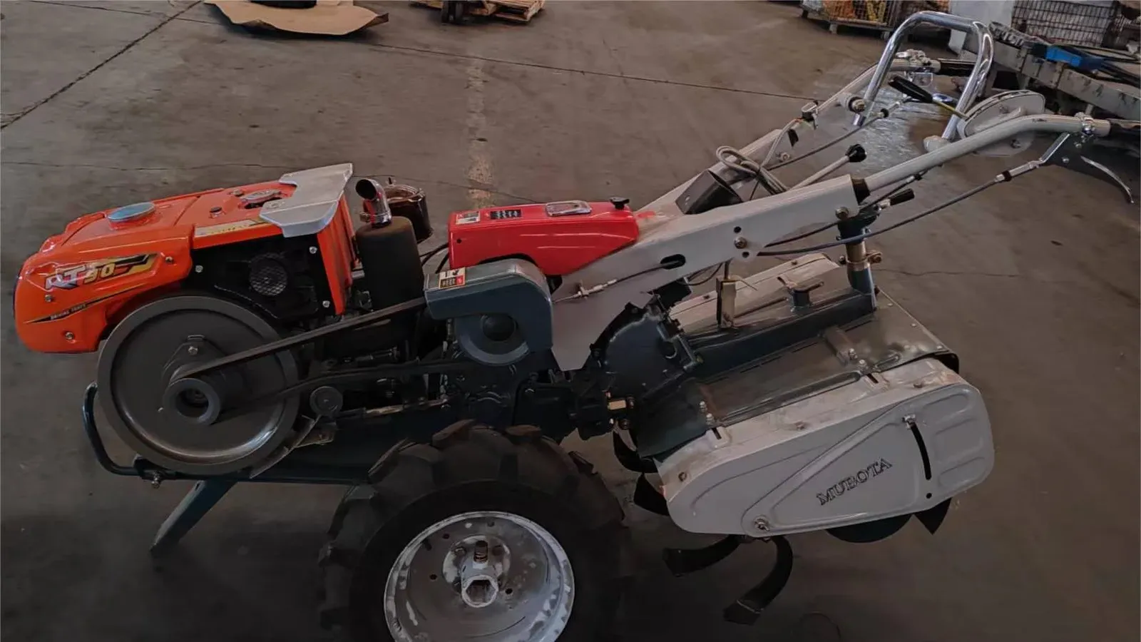
Search a supplier directory for "M80 power tiller" and you will not find one machine. You will find a class: the same chassis name quoted at 7 hp in one listing and 10 hp in the next, with a rotary width to match each. The label describes a platform, not a fixed build.
Closing that gap is the job of an M80 power tiller configuration, and it is why the order of the decisions matters more than the numbers on any one quotation. Engine, tilling width, wheel track, gear selection and implements are not a menu you pick from; each one constrains the next. Decide them in the wrong order and every later choice sits on the wrong machine.
This guide works through the M80 in that order, so the brief you send a supplier is a configuration you can defend.
What an M80 configuration actually decides
The M80 is a compact platform rated for a 7–10 hp engine. Its recorded figures are what a buyer configures against, because they rule whole categories of work in or out before any other choice is made.
M80 chassis record | Value |
|---|---|
Compatible engine range | 7–10 hp |
Overall dimensions | 2050 × 710 × 1235 mm |
Weight without engine | 179 kg |
Standard rotary tillage | 480 mm, 14 blades |
Maximum rotary tillage | 600 mm, 16 blades |
Walking gears | 6 forward / 2 reverse |
Rotary speed selections | 4 speeds (two set at the auxiliary sprocket) |
Tire | 5–12 |
Wheel track | 390–780 mm |
Brake | Internal expanding |
Main clutch | Dry multi-plate |
Steering clutch | Jaw type |
Power path | Engine to main shaft: 2 V-belts; main shaft to wheel axle: gears; gearbox to blade shaft: chain |
Two things follow from that table. A machine 2050 mm long and 710 mm wide is built for plots a four-wheel tractor cannot enter — but it is still a two-meter machine, so access and turning space enter the decision before horsepower does. And 179 kg is the bare chassis: fit an engine and the working machine is heavier, which is the number that decides whether one operator can hold it on soft ground all day.
Where this platform sits against the heavier one in the range is a separate decision — the power tiller configuration hub carries the range alongside it — and the published figures are repeated on the M80 platform page. This article assumes the compact platform is the right one and walks its configuration in order. One disclosure before the detail: the platform used as the worked example here is one SUNTEC builds, and every check below is written to hold up against our own numbers as well as anyone else's.
The order, and why it is fixed
Six decisions, in sequence:
- Field envelope — access, turning space, slope, soil.
- Engine and starting method.
- Tilling width and blade set.
- Wheel track and tire.
- Gear and rotary-speed selections.
- Implements, then what they mean for the quotation.
The sequence is not arbitrary. Tilling width sets how many passes a plot needs. Blade count and rotor speed set how hard the engine has to work at that width. Wheel track decides whether the machine can follow the rows it is meant to till. And the implement package changes the load the engine was sized for. Choose width before the envelope, or engine before the work, and you get a machine that is within specification and still wrong for the field.
Start with the field envelope, not the horsepower
The envelope is what fits through the gate, turns at the headland and stays upright on the slope. On the M80 it is fixed in two dimensions — 2050 mm long, 710 mm wide — and adjustable in one, because the wheel track moves.
Measure, in this order:
- the narrowest access point on the route into the plot, and the width the machine must pass through;
- the headland room needed to turn a 2,050 mm machine around;
- the row or bed spacing the wheels have to straddle without crushing plants;
- the slope, the soil type, and whether the field holds water.
If the answers say the plot is wider than the machine can till in a sensible number of passes, or the soil is heavy enough that 7–10 hp at 600 mm will not pull a rotor at depth, the honest conclusion is that the compact platform is the wrong machine — not that it needs a bigger engine on the same chassis. Writing the envelope down first also produces the brief a supplier needs; the field selection guide sets out how to build it field by field.
The M80 sits in a category that carries most smallholder tillage. The FAO's mechanization review notes that two-wheel tractors are not counted as "tractors" under the standard FAO definition at all, even though in Bangladesh machines of this class perform about 90% of tillage operations (FAO, Mechanization for Rural Development). The practical reading for a distributor is that demand for this class is real and large — but it is also local. A configuration that sells in one market can miss the next one entirely, which is one more reason the envelope comes before the numbers.
Fix the engine and the starting method
The M80 chassis accepts a 7–10 hp engine. That range is wide enough to make the engine a real decision rather than a formality, and the reference engine recorded for the platform shows why the headline number is not enough on its own.
RT90DI engine reference | Value |
|---|---|
Displacement | 487 cc |
Maximum output | 9 hp (6.62 kW) at 2,400 rpm |
Continuous output | 8 hp (5.88 kW) at 2,400 rpm |
Fuel tank | 10 L |
Starting | Hand crank or electric start |
Net weight | 89 kg |
Compression ratio | 18:01 |
Two figures matter more than the rest. The first is the 10 L tank, which sets how long the machine runs between refills — a working-day question, not a spec-sheet one. The second is the gap between the 9 hp maximum and the 8 hp continuous output.
That pair is not a rounding difference. Engine ratings are defined by the duty they can sustain: a generator data sheet that follows ISO 3046 defines the higher, intermittent figure as power available for a period not exceeding one hour in any twelve hours of continuous running. Read the same way, a maximum rating is a ceiling the engine can touch and a continuous rating is what it is meant to hold all day. For a tiller working a paddy plot, the continuous figure is what decides whether the machine keeps its rotor speed in wet soil — and it is the reason a 7 hp unit is not simply a 10 hp unit with the throttle turned down.
The starting method is the other half of the decision. The recorded engine offers hand crank or electric start, and the choice is a market one: distributors selling into markets where buyers already expect a battery and a key will not accept hand crank whatever the price difference, and distributors selling where a battery is an unreliable overhead will want the opposite.

If you are still deciding how to read a rating against a duty cycle, the specification guide covers the difference between a machine figure and a working result.
Set the tilling width and the blade set
Tilling width is the decision most buyers make first and should make third. On the M80 the confirmed public range is 480 mm and 600 mm, and the platform's own specification table lists both: 480 mm as the standard 14-blade set and 600 mm as the maximum 16-blade set. The width you configure is the width that has to appear in the quotation — not a number to assume from the model name.
Width is a trade, and the trade is passes against load. A 480 mm rotor on a 2,050 mm machine still needs a fixed number of passes to cover a plot. A 600 mm rotor covers more ground per pass, but the same engine is now driving a wider cut through the same soil, and the wider cut is not free.
The blade set is the other half of the choice, and it is not a matter of taste. Rotary tillage equipment is specified by working width and blade geometry rather than by engine size: TNAU's farm machinery reference lists a rotavator by working width, by an L-shaped blade 7–10 mm thick and by a rotor shaft turning at 210–237 rpm. Those are the numbers that decide how soil breaks up, and on the M80 the equivalent choices are the 14-blade and 16-blade sets.
Put the two together against the envelope from step one:
- narrow beds, tilled one or two passes wide — the 480 mm set leaves cleaner edges and keeps the engine away from its ceiling;
- open plots and dry soil, multiple passes acceptable — the 600 mm set cuts the number of passes;
- wet, heavy or trashy soil — width is the first thing to give up, because rotor speed is what keeps the machine moving.

If width and soil are fighting each other, change the width before you change the engine. A wider rotor on an engine already running at its continuous rating is the commonest way a configuration that reads well on paper underperforms in the field.
Confirm the gear and rotary-speed selections
The M80 records 6 forward and 2 reverse walking gears, and four rotary-speed selections, two of which are set at the auxiliary sprocket. The power path is worth writing out in full, because it tells you which parts are service items.
Stage | M80 record |
|---|---|
Engine to main shaft | 2 V-belts |
Main shaft to wheel axle | Gears |
Transmission to blade shaft | Chain |
Main clutch | Dry multi-plate type |
Steering clutch | Claw type |
Brake | Inner Expansion Type |
Four things follow for anyone configuring the machine.
Belts, chain and blades are the wear items in that path, and they are the parts a distributor is asked for first: a configuration is only as good as the parts channel behind it. Rotary speed is a selection, not a fixed characteristic — four options with two set at the auxiliary sprocket mean the same machine can be set for finer tilth or faster travel, which also means a demonstration set up for one soil type proves less than it appears to. Six forward and two reverse is a configuration fact, not a productivity claim: gear count says nothing about ground speed or field capacity without the ratios and the conditions, so ask which forward gears the supplier intends for tillage and which for transport rather than reading capacity off the count. And the clutch and brake types are specified — a dry multi-plate main clutch, a jaw-type steering clutch and an internal-expanding brake — which is what an operator trains on and what a service plan has to be able to replace.

Match wheel track and tire to the plots you serve
Wheel track is the dimension that decides whether the machine works with the crop or over it. The M80 adjusts from 390 mm to 780 mm on 5–12 tires, which covers narrow raised beds at one end of the range and a wider dry-land stance at the other.
Set it by the row. Measure the spacing the wheels must straddle and the width the plot allows, then take the track that fits inside both. Set it too wide and the wheels crush the plants the implement is meant to leave standing. Set it too narrow on a slope and the machine turns tippy, and the wheels ride down into the furrow the rotor has just cut. On soft or wet soil the tire and the track act together: the narrower the track, the more load per wheel, and the deeper the wheels sink.
The adjustment is mechanical, and it is one configuration point a distributor should settle at quotation rather than at delivery, because it changes with the market. The same chassis delivered to two territories can leave the factory on two different track settings and two different tire specifications.

Treat the implements as part of the configuration
Implements are where a defensible configuration is most often lost. A rotary tiller, a plough, a trailer and traction equipment each change the task, the load and the operating procedure, and each has to be matched to the width, the engine and the wheel track already fixed. A request that names a machine and stops there is an incomplete request.
For every implement, write down four things: the job it does, the field condition it works in, how often it will be used, and the interface it attaches to. Then check one interaction that is easy to miss — an implement wider than the track the wheels leave is an implement that re-tills its own footprints, and one that needs more power than the continuous rating allows is an implement the machine will not carry all day.
The M80's implement set is grouped in the implements and attachments hub, where the families are split by how they mount and what they are used for. Read that grouping before writing a list, because implement families are quoted differently depending on whether they hang off the chassis or run behind it — and the answer changes what the quotation has to cover.
Convert the configuration into a quotation brief
The point of walking the order is that it turns into a brief a supplier can answer. Write it in the same sequence and the gaps become obvious:
- Field: access width, turning space, row or bed spacing, slope, soil, wet or dry.
- Engine: output within the 7–10 hp range, and the starting method.
- Tilling width: 480 mm or 600 mm, and the blade count.
- Wheel track: the setting the rows require, and the tire.
- Gears: which forward gears for tillage, which for transport.
- Implements: job, condition, frequency, mounting.
- Support: manuals, operator training and the wear parts the quote covers.
- Open items: everything still unconfirmed — packing, documentation, and any market requirement you have not settled.
That last line matters. A brief that names its open items gets a quotation that answers them; a brief that hides them gets a price and a follow-up email. The distributor procurement workflow covers how the brief becomes an order — and once the envelope and the configuration are settled, send us the field and configuration details and we will work the machine to them.