





A Compact Power-Tiller Platform for Routes and Plots Where Handling Sets the Limit
MUBOTA M80
MUBOTA M80 Power Tiller for Tight Access.
The MUBOTA M80 power tiller gives distributors a starting point for plots where the route, turning room and working width matter as much as the task itself. Its 179 kg chassis without engine, 7–10 HP compatible range, 6F / 2R transmission and 480 or 600 mm tilling setups provide the documented basis for that discussion.
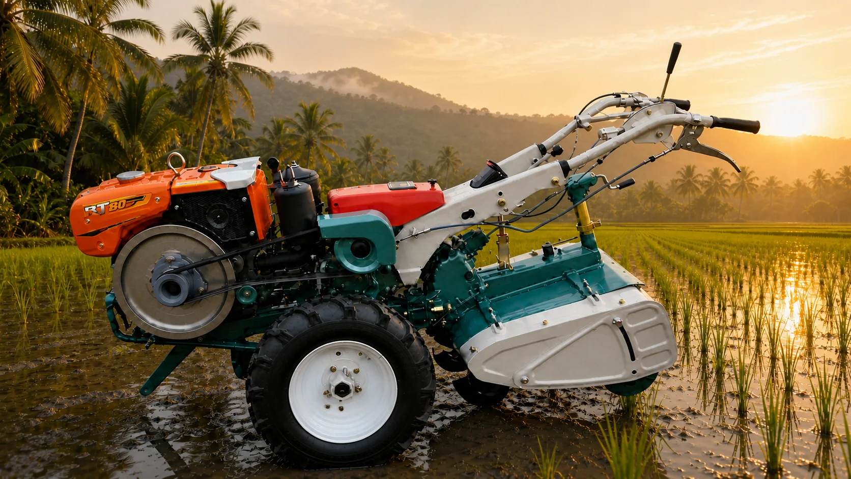
- Power range to configure
- 7–10 HP
- Chassis weight without engine
- 179 kg
- Travel-speed selection
- 6F / 2R
- Working-width choice
- 480 / 600 mm
M80 Advantages
Precision Gearing, Lightweight Handling and Lower Ownership Cost.
M80 combines high-precision gears with a 179 kg chassis without engine. The result is a durable, flexible platform designed for easier handling and a lower Total Cost of Ownership (TCO) across its working life.
High-precision gears for longer life
High-precision gear manufacturing supports stable power transmission, longer service life and fewer avoidable drivetrain interventions when the machine is correctly operated and maintained.
Lightweight and easy to operate
At 179 kg without the engine, the M80 chassis is designed for flexible handling, repeated turns and easier operation in smaller plots and restricted access routes.
Lower fuel and ownership burden
The lighter platform can reduce the mass the engine must move, supporting lower fuel consumption and Total Cost of Ownership. Actual results depend on the engine, soil, implement, load, maintenance and operating practice.
Inspect Before Specifying
Review Five M80 Angles in One Inspection Board.
The combined board keeps all five mechanical views together, while the inspection index below preserves what procurement and service teams should verify from each angle.
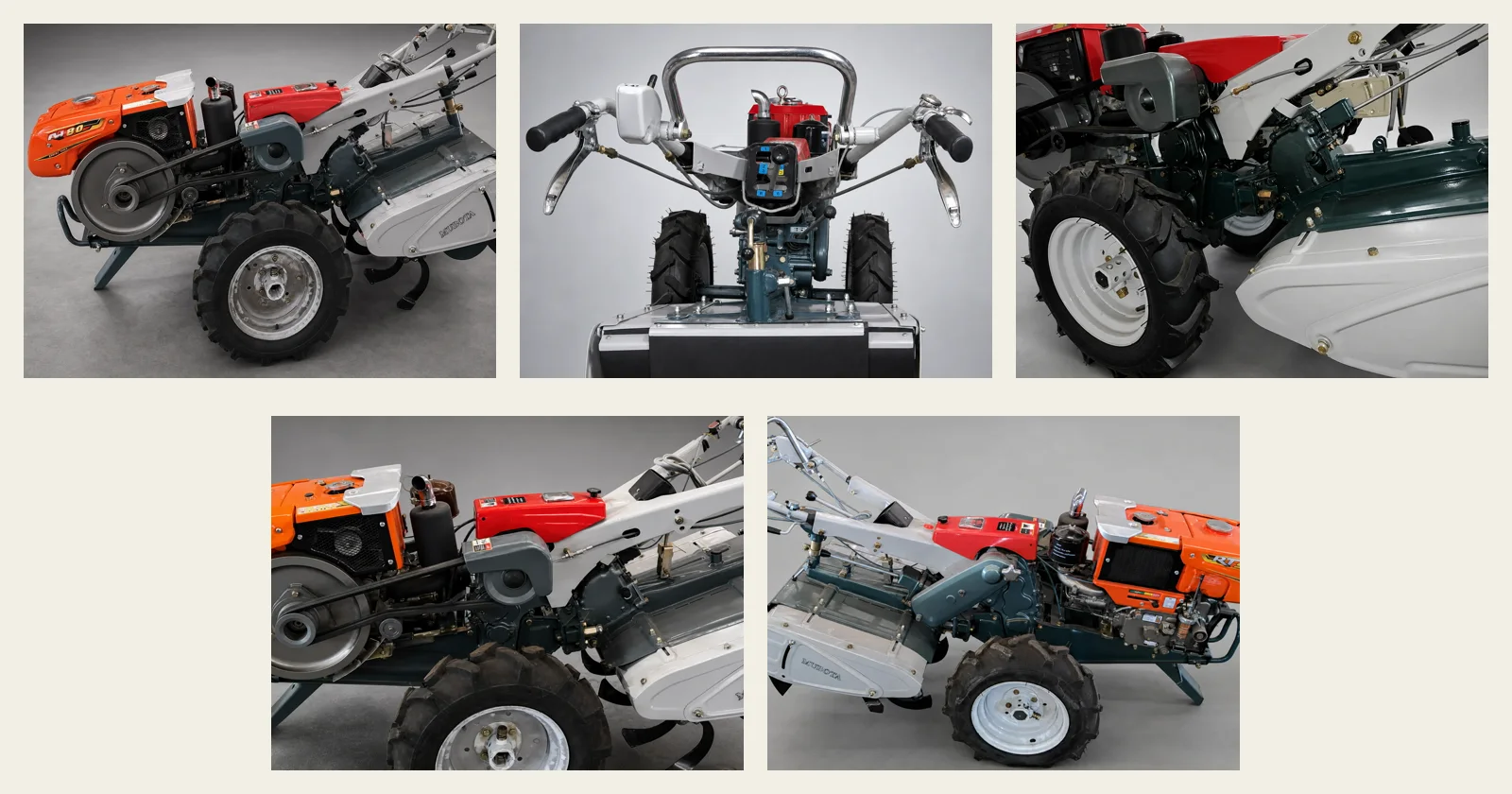
Combined mechanical view
Five-angle M80 inspection board
Read the board from left to right to compare the complete side profile, front control area, rotary-side drive, belt-drive relationship and opposite-side chassis in one place.- 01
Complete-machine view
Side profile
Use the side profile to review how the engine, chassis, wheels and rotary-tiller cover are arranged as one working package. - 02
Control and guard view
Front view
Check the handlebar arrangement, engine position and front protective structure against operator access and handling requirements. - 03
Tiller drive view
Rotary-side view
Review the drivetrain, protective cover and rotary-side structure before confirming the selected working-width arrangement. - 04
Engine and transmission
Belt-drive side view
This angle makes the engine-to-belt-drive relationship visible for configuration review and later parts identification. - 05
Chassis and rotary housing
Opposite-side view
Use the opposite profile to verify the wheel, handle frame and rotary housing from the side not shown in the main product view.
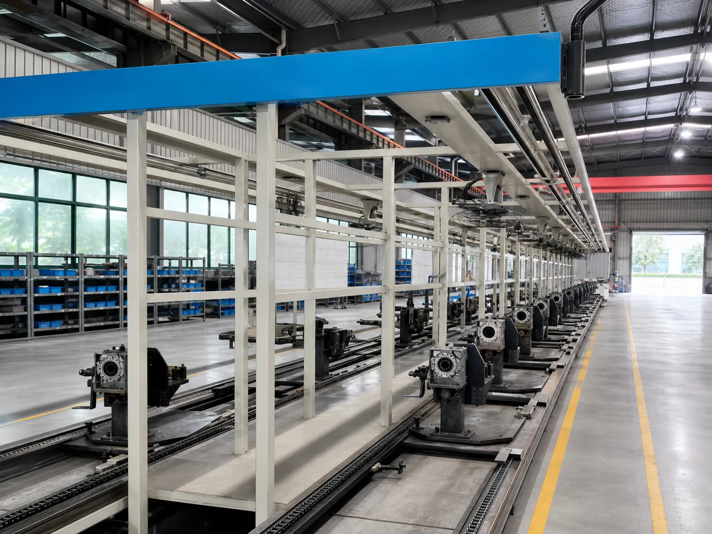
M80 assembly context
Review the Workshop Context Behind the M80.
The workshop record shows a long production line arranged around repeated gearbox and chassis work positions. It gives procurement teams a visible assembly context to review without representing a production-capacity, automation or output claim.
Environment-cleaned and relit M80 workshop photograph; the production-line structure and equipment layout were retained.
Field-Operation Footage
See the M80 Working in Wet-Paddy Conditions.
This customer-supplied field clip shows an M80 working through wet paddy soil. Use it to understand the operating context; confirm the final engine, working width, wheels and implement scope in the quotation.
M80 Paddy Field Demonstration
Watch continuous rotary-tillage operation in a wet-paddy setting.
Field footage is context only; confirm the supplied configuration and equipment package before quotation.K75-Interchangeable Mechanical Parts
Assemblies & Spare Parts That Can Be 100% Interchangeable with K75.
M80 Interchangeability covers the key assemblies and service parts shown here. For every replacement order, match the part by installed position, part number where available and a clear photograph; K75 is a third-party product reference and no affiliation is implied.
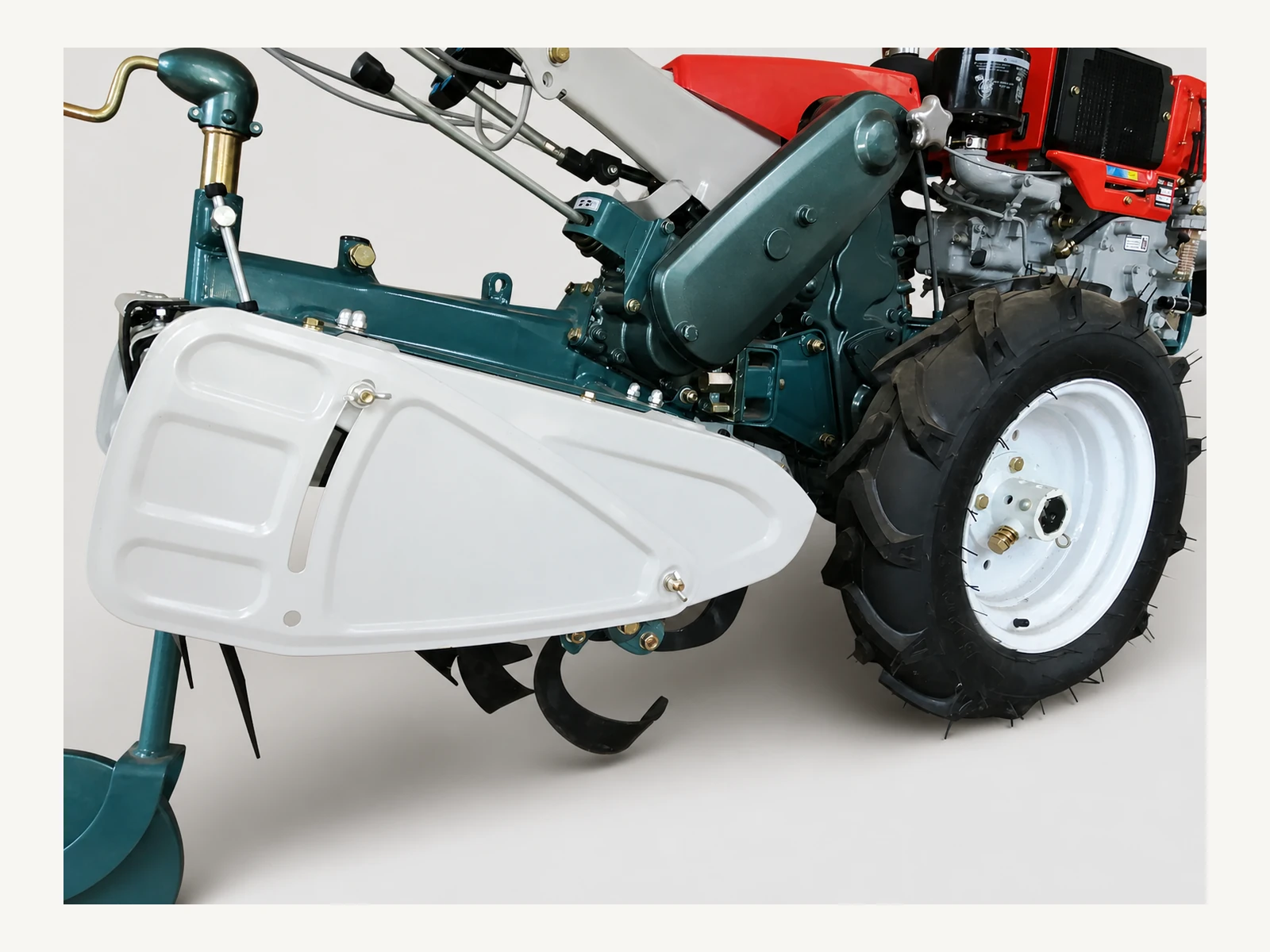
Mechanical controls
Drivetrain and control detail
Use this view to locate the clutch, brake, belt drive and rotary-side controls when describing a configuration or reporting a fault.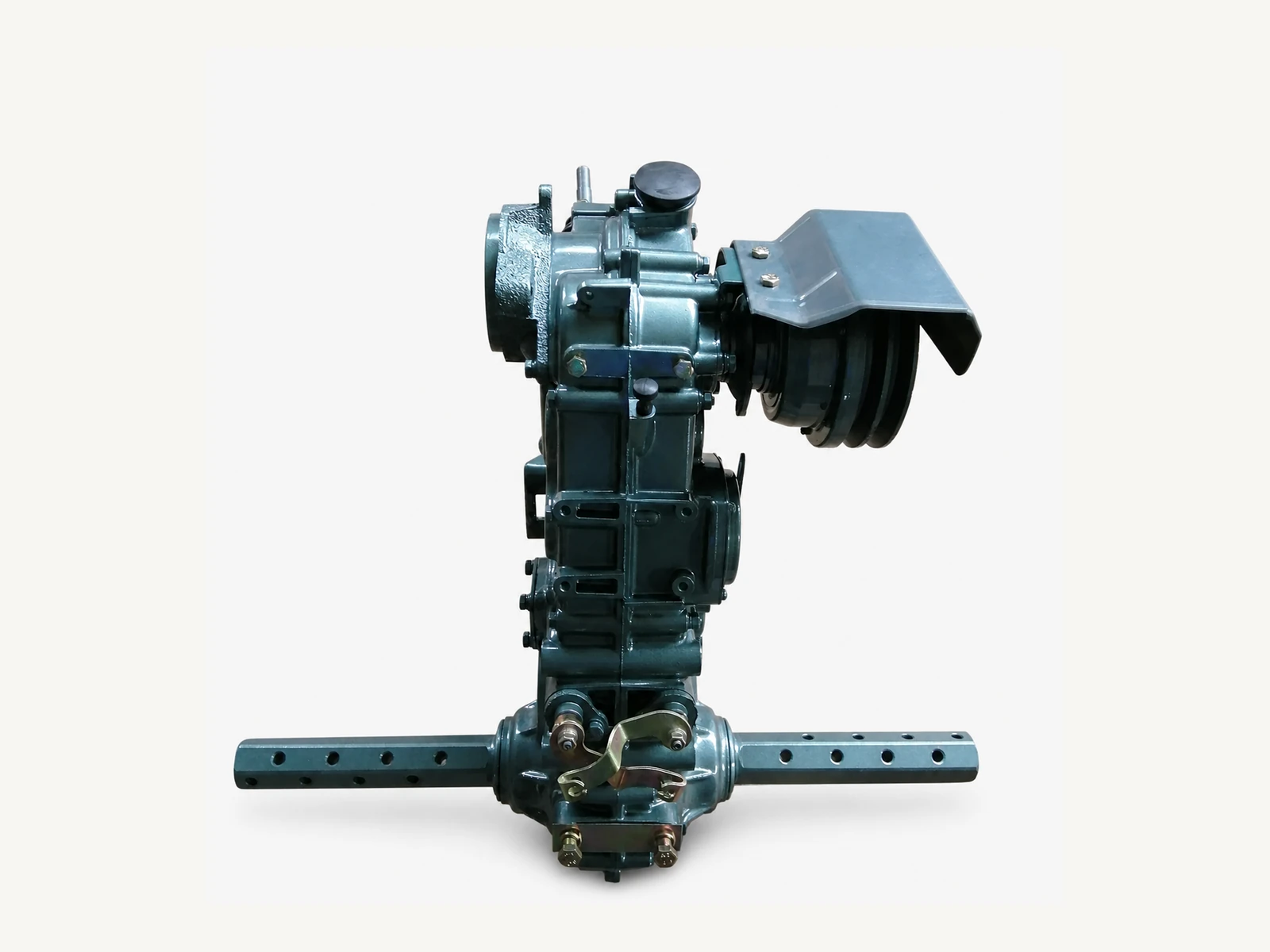
Core M80 assembly
Aluminium gearbox assembly
The aluminium-alloy gearbox is a defining M80 feature, transferring power from the engine belts through gears to the blade-side chain drive.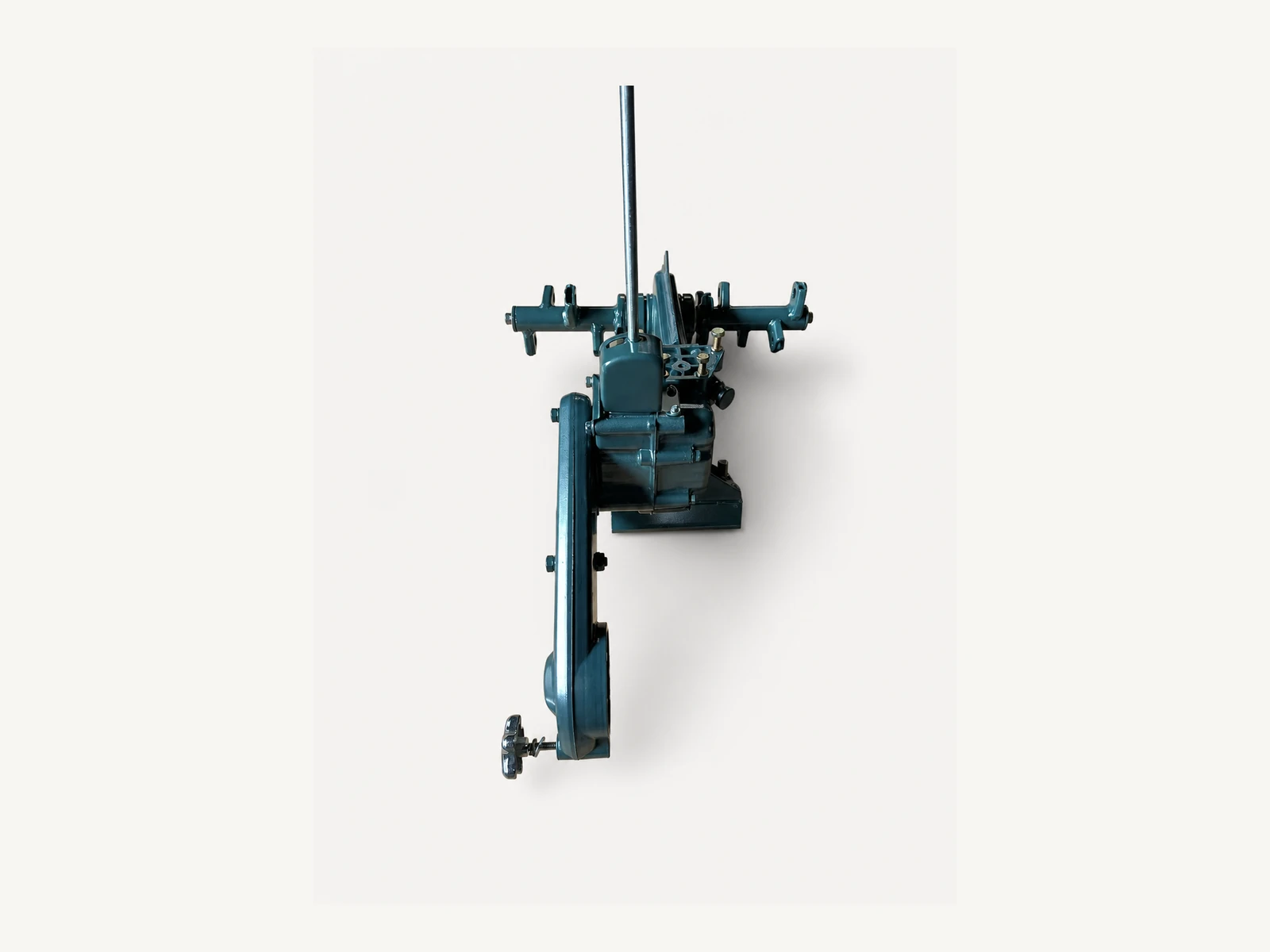
Rotary implement drive
Rotary attachment gearbox
The rotary gearbox, shaft line and mounting brackets form a separate tilling assembly that should be matched to the selected working width.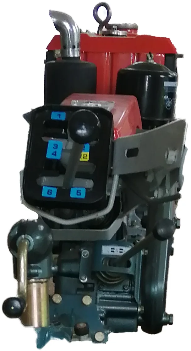
6 forward / 2 reverse
8-speed gear selector
The selector displays the six forward and two reverse travel positions used by the M80 transmission and provides a clear service-identification reference.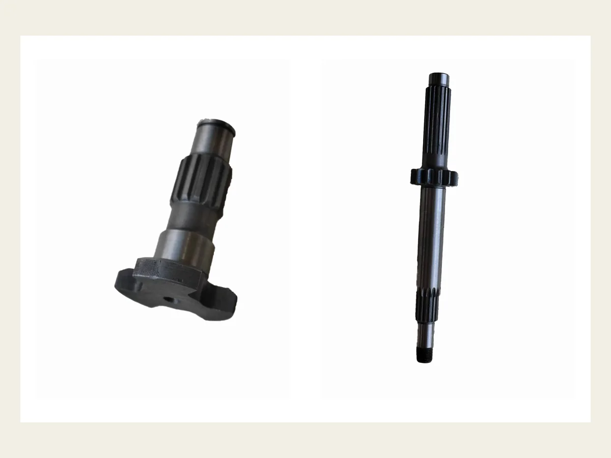
Core M80 service parts
M80 shaft set
Compare shaft length, stepped profile, spline geometry and installed position before confirming a replacement; the paired view keeps both documented M80 shaft types visible.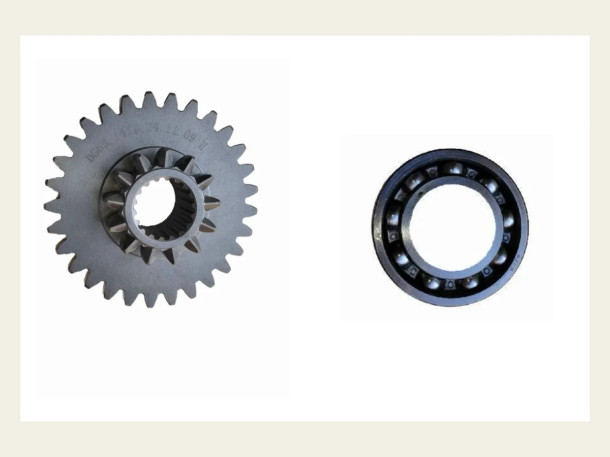
Core M80 service parts
Matched gear and bearing set
Transmission gears and bearings must be identified as a matched service request using their markings, dimensions and installed position rather than a generic part name.Build the Working and Service Package
Choose the Working Implements Matched with the Machine.
Working implements are optional, separately quoted selections rather than standard machine supply. Match the required implement to the intended work, then confirm its mounting hardware and complete scope in the quotation.
Optional cultivation implement
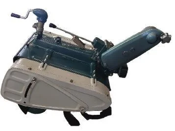
Rotary cultivator
Select the 480 mm / 14-blade or 600 mm / 16-blade rotary arrangement according to plot width, soil and required coverage.This is an optional, separately quoted implement; confirm the working width and blade arrangement in the machine package.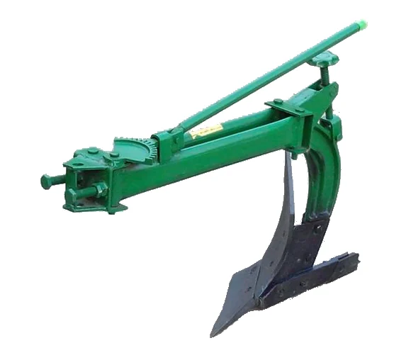
Optional ploughing implement
Single-furrow plough
Add the single-furrow plough only when furrow opening is part of the end customer's planned work.This is an optional, separately quoted implement; confirm the plough and connection hardware before order approval.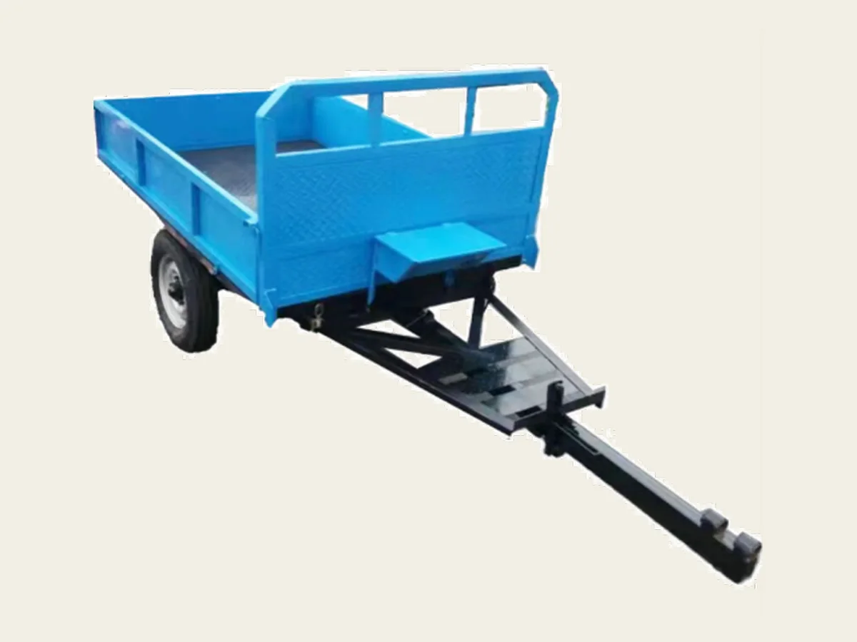
Optional transport connection
Small trailer connection
Add the blue single-axle trailer when short-distance transport is part of the buyer's planned farm work.This is an optional, separately quoted transport package; confirm the trailer body, axle, hitch, pin, coupling hardware, intended load and local transport requirements in the quotation.Compare on a Confirmed Basis
Separate Fixed M80 Chassis Facts from Engine Configuration Choices.
Review the customer-issued M80 chassis and RT90DI engine workbook alongside the HTML summary below. The downloadable source records the reference configuration; confirm the final engine, starting method, implement package and commercial terms in the quotation.
The specification PDF summarises the M80 chassis and RT90DI engine reference configuration. Confirm the final engine, starting method, working width and implement package in the quotation.
- Model
- MUBOTA M80
- Compatible engine range
- 7–10 HP
- RT90DI engine reference
- 487 cc; 9 hp maximum / 8 hp continuous at 2400 rpm
- Transmission
- 6 forward / 2 reverse
- Gearbox
- Aluminium alloy
- Tilling width
- 480 mm / 14 blades standard; 600 mm / 16 blades maximum
- Tilling speeds
- 4 settings
- Weight without engine
- 179 kg
- Overall dimensions
- 2050 × 710 × 1235 mm
- Tires
- 5–12
- Wheel tread
- 390–780 mm (15-3/8–30-3/4 in.)
- Brake
- Inner-expansion type
- Clutch system
- Dry multi-plate main / claw-type steering clutch
- Power transmission
- 2 V-belts → gear → chain
Use MUBOTA M80 as the chassis reference on enquiries, quotations and service-part requests.
Treat 7–10 HP as the compatible chassis range, not as one fixed supplied-engine output.
The customer-issued workbook records hand or electric starting for this reference. Confirm the final engine and starting method in the quotation.
Use the 6F / 2R travel range when comparing operating-speed flexibility with another platform.
The aluminium-alloy gearbox is a defining difference from the heavier iron-gearbox GN12 platform.
Confirm 480 or 600 mm before quotation; the working width changes the rotary arrangement and blade count.
Four settings are documented; two require an auxiliary-sprocket change and should be explained to the operating team.
This is the chassis weight without engine; compare final machine weight only after engine and implement selection.
Use the complete-machine dimensions when checking field access, storage and packing requirements.
Confirm tyre and any field-specific wheel requirements as part of the working configuration.
Use the adjustable tread range when checking row spacing, access width and stability requirements.
Mechanical inner-expansion brake construction.
The chassis uses a dry multi-plate main clutch and claw-type steering clutch.
Engine to main shaft: 2 V-belts; main shaft to wheel axle: gear; transmission to blade axle: chain.
Make Later Service Easier to Trace
Identify the System Before You Name the Part.
A useful service request identifies more than a likely part name. Organise M80 requests by machine system, installed position and visible details so the matching discussion starts from evidence.
Clutch and transmission
Clutch plates, clutch pulley, gears, bearings, oil seals, selector parts and drive shaftsFor clutch or transmission requests, identify the machine configuration, installed position and visible profile before asking for a matching part.
Rotary tiller drive
Rotary shaft, chain case, drive chain, sprockets, blades, blade bolts and sealsState whether the machine uses the 480 or 600 mm rotary arrangement, then identify the required part within the chain, sprocket, shaft or blade system.
Controls and cables
Gear selector, accelerator cable, main/side cables, levers, supports and handle fittingsShow the affected selector, lever or cable at both ends so the service team can distinguish the control path and connection type.
Wheel and hitch hardware
Gearbox axle, axle pins, hubs, wheel hardware, hitch pin, bush and mating hardwareRecord the wheel-tread setting, mounting side and connected implement when identifying axle, hub or hitch hardware.
Turn M80 Fit into a Supplied Machine
Build the Package Around the Route and Task.
The M80 name does not define the delivered machine by itself. Use these three decisions to connect the field brief, engine setup, working equipment and delivery scope.
- 01
Define the field and operator
Share the destination market, customer type, plot size, access width, terrain or soil conditions and the jobs the machine must perform.
- 02
Choose the engine and tilling setup
Confirm the required power range, current engine model and starting method, then select the 480 mm / 14-blade or 600 mm / 16-blade rotary arrangement.
- 03
Confirm implements, initial parts and packing
List the verified implements, initial service parts, order quantity, destination and packing requirements that must appear in the commercial proposal.
Ready to Scope an M80 Package?
Send the Access and Work Details First.
For a useful M80 proposal, include the destination, customer type, plot and access conditions, primary jobs, preferred engine and starting method, tilling width, required implements, initial service parts, quantity and packing needs.
The final engine model, starting method, implement compatibility, included service parts and packing scope are confirmed in the quotation for the selected market and order.