
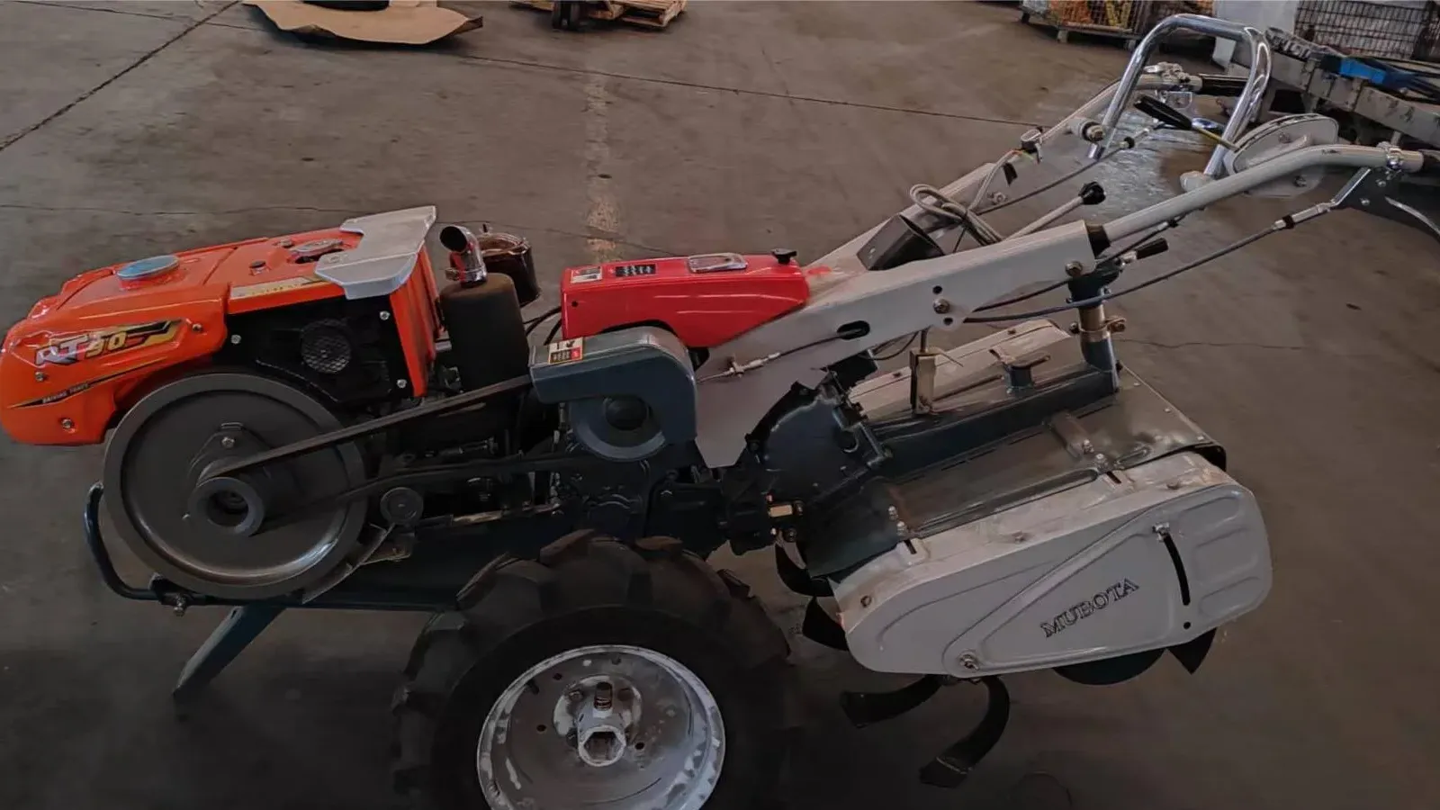
A grower with eight hectares of fruit trees and a grower with eight hectares of open field are asking for the same machine and getting completely different answers. The engine they need is roughly the same. What separates the two orders is geometry: how wide the machine is, how much room there is between the trunk line and the next row, how much space is left at the end of the row to turn, and whether the machine can physically get from one block to the next.
That is why a search for power tillers for orchards and row crops tends to end in retail pages that rank garden tillers by horsepower, and why those pages do not help a distributor quoting a machine for a customer's split into four blocks with a 3.4 m row spacing. This guide works the problem the other way round: it sets out the four dimensions that decide whether a walk-behind platform fits, the numbers a grower's planting plan fixes before any machine is chosen, and the list of things to measure before a quotation is written. It is part of the field conditions cluster because nothing here is about brand or power — it is about the space the machine has to work in.
What orchard and row-crop access actually measures
"Access" is a word that hides four separate measurements. Each one can be taken with a tape measure in an afternoon, and each one can disqualify a machine on its own:
- Alley width — the clear distance between the canopy edge of one row and the canopy edge of the next.
- Under-tree strip width — the band along the trunk line that is kept free of competing vegetation, and which is usually where cultivation is actually wanted.
- Headland depth — the space at the end of the row where the machine is turned back into the next alley.
- Route to the block — gate width, path width, slope and any crossing on the way in.
The first two are not the buyer's to choose. They were set by the planting plan — apple, pear, stone fruit, citrus, or vine — and on modern intensive plantings they are tight by design. Penn State Extension's apple orchard system blueprint specifies tree spacing of three to four feet within the row and 11 to 12 feet between rows, a four-foot-wide herbicide strip in the tree row, and a canopy trained so that tree height stays at about 90% of the cross-row spacing (Penn State Extension).
Two numbers from that description matter more than the rest. Eleven to 12 feet is 3.35 to 3.66 m of alley — which sounds generous until the machine, its handlebars and the operator are subtracted. And four feet is 1.22 m of vegetation-free strip, which is the band a tiller is usually bought to work. The same logic runs through orchard and vineyard plantings alike, and through narrow row crops: the alley is the machine's corridor — the space where inter-row cultivation, spraying and mowing all happen — the strip along the trunk line is its work, and neither was sized around a machine.
What the planting fixes | Typical figure | What it constrains |
|---|---|---|
Between-row spacing | 11–12 ft (3.35–3.66 m) on intensive apple | Alley the machine and operator must share |
In-row tree spacing | 3–4 ft (0.91–1.22 m) | How often the machine passes a trunk |
Under-tree strip | 4 ft total on the Penn State blueprint; 2 ft or less per side on dwarf trees, up to 6 ft per side on mature semi-dwarf trees (New England Tree Fruit Management Guide) | The width of cut that is actually useful |
Canopy / tree height | Trained to about 90% of cross-row spacing (≈3 m on an 11 ft alley) | The top of the canopy; limb clearance is not specified — measure the lowest limb |
Row length | Farm-specific — measure it | Walking distance and turnaround frequency |
The four dimensions that decide whether a walk-behind platform fits
A walk-behind platform — sold as a power tiller, a walking tractor or a two-wheel tractor depending on the market — is a small set of published numbers, and every one of them maps onto one of the four measurements above. On the two SUNTEC platforms those numbers are recorded in the published specification sheets:
Published figure | M80 chassis | Super 12 / GN12 chassis | What it decides on site |
|---|---|---|---|
Overall dimensions (L × W × H) | 2050 × 710 × 1235 mm | 2950 × 980 × 1240 mm | Whether the machine clears the alley, the gate and low limbs |
Wheel tread settings | 390–780 mm | 810 / 750 / 690 / 630 / 570 mm | How much of the alley the wheels claim |
Tilling width | 480 mm standard, 600 mm optional | 480 or 600 mm (the published specification table records the 600 mm configuration, with 18 or 24 blades) | How much of the under-tree strip one pass covers |
Minimum ground clearance | — | 210 mm | What it can cross: ruts, stones, irrigation lines |
Gears | 6 forward, 2 reverse | 6 forward, 2 reverse | Whether the row end is turned on the clutch or on the reverse gear |
Steering | Dog-clutch steering clutches | — | Whether the machine can pivot on one wheel |
Brake | Internal expanding | — | Control on a slope or a loaded path |
Weight without engine | 179 kg | 470 kg | What it takes to move it: a ramp, rollers or a hoist for the 179 kg machine, wheels or a trailer for the 470 kg one |
Engine class | 7–10 hp | 12.5 hp maximum output | Work rate, not access |
Read the table as an access document rather than a specification sheet, and three things stand out.
Width is set by tread, not by the chassis. The 710 mm and 980 mm figures are the machines as built. The tread settings change the footprint: the M80's 390–780 mm range is a 390 mm spread, the GN12's 570–810 mm range is 240 mm. Tread is measured between tyre centrelines, so the space actually occupied is the tread plus one tyre width — which is why a machine at its widest tread setting can be wider across the wheels than the single chassis width in the specification table suggests. If a block is planted tight, the tread setting is the first thing to agree, and it should be agreed before the machine is crated, not after.
Length is the number nobody asks about. 2050 mm on the M80 and 2950 mm on the GN12 is the overall length in the published dimension figures — the distance the machine needs in a straight line, which is also the reason a row end that looks adequate on a plan turns out not to be.
Weight decides who can recover it. 179 kg without engine on the M80 and 470 kg on the GN12 are the figures that matter when a machine is stuck in wet clay at the end of a row, or when it has to be loaded onto a trailer. On orchard work, where a machine may be moving between blocks several times a season, that is a real operational figure, not a shipping detail.

Seen head-on, the number that decides whether the machine enters a block is the tyre-to-tyre footprint at the chosen tread setting — not the single chassis width in the specification table.
Tree-line clearance: what the machine takes out of the alley
The useful question under the trees is not "how wide does it till" but "how much of the strip does one pass actually clear, and what does that leave".
A four-foot strip is 1.22 m of ground to keep free. Worked as one full-width pass, a 480 mm cut would cover 39% of it and a 600 mm cut 49% — which is why a strip that wide is never worked in a single pass. The practical pattern is one pass down each side of the tree line: on a dwarf planting the vegetation-free band is often two feet or less on each side of the trunk, so each pass has about 0.61 m to cover, and a 480 mm cut covers roughly 79% of that side while a 600 mm cut covers nearly all of it. The width figure therefore changes how many passes a row needs and how closely the machine has to track the trunk — this is strip cultivation along the tree line, not full-floor tillage — but it does not decide whether the job is possible.
Two cautions follow from the same geometry.
Keep the cut shallow near the trunk line. The strip exists to reduce competition for water and nutrients, and the roots that matter are in it. A rotary tiller working the strip is a management tool for the top layer, not a primary tillage pass, and the depth setting should be the shallowest that does the job. Soil resistance, machine weight and implement choice interact here in ways that are covered separately in soil resistance, weight and implement matching.
Check the height before the width. The Penn State blueprint caps tree height at about 90% of the cross-row spacing — roughly 3 m on an 11 ft alley — but that figure describes the top of the canopy, not the underside of it. The clearance that decides whether a 1.24 m machine passes is the lowest limb over the alley, and a planting specification does not give it: on a trained fruiting wall the first branches can sit barely a metre above the ground. Measure the lowest obstruction at the point where the machine will pass, on the outside row as well as inside the block, and treat a branch close to the machine's height as a no.
On a wet orchard floor, the wheel equipment decides whether the pass happens at all. Steel traction wheels and wheel extensions change the contact and the footprint rather than the engine, and the trade-offs are set out in steel traction wheels and wheel extensions.

The width that has to clear the trunk line is the guard and the drive wheel, not just the tines. In a strip narrower than the machine, the pass is planned around the tree, not through it.
Turning at the row end is the real bottleneck
In field machinery terms the headland is the area at the end of the track that a machine needs in order to turn onto the next parallel track (Springer, Precision Agriculture). For a tractor-drawn implement that is a wide strip. For a walk-behind machine it is smaller but not free, and it is the measurement most often skipped.

The GN12 platform with the rear-seat option fitted, photographed on hard standing. What the photograph cannot tell you is the turning room at the end of the row — that is a measurement, not a specification.
Three features of these platforms change what a row end has to be:
- Steering clutches. The M80 uses dog-clutch steering, which disengages one drive wheel so the machine pivots around the other. That is how a walk-behind machine turns in a space far shorter than its own length would suggest — but it pivots on a wheel, so the pivot point has to be clear of the trunk line.
- Two reverse gears. Both platforms carry six forward and two reverse gears. The low reverse is what places the machine back into an alley after a turn, and the reason machine reversing is a routine part of orchard work rather than an exception.
- Brakes on the machine, none on the operator. The M80's internal expanding brake is the only thing holding a machine that is being turned on a slope. It should be checked and adjusted before the season, not after the first slip.
The safety guidance for farm vehicle routes is written for tractors and telehandlers, but one line applies directly to a walk-behind machine working between rows: routes should be arranged to reduce the need to reverse, for example by adding turning circles or using one-way systems (HSE, safe workplace transport). On an orchard block that translates into a simple rule — plan the direction of travel so the machine turns into open ground at the row end, rather than backing out between two rows of trunks.
How much headland is enough cannot be answered from a catalogue. It is the alley width plus whatever the machine needs to swing its handlebars through a turn, and it is best established by taking the machine to the block and turning it empty, at both ends, before the season starts. The measurement method for that test is set out in measuring field access and turning space.
Getting the machine between blocks
Orchard work is rarely one block. A grower with four blocks wants one machine that reaches all four, and the route between them is a separate set of measurements from the alley: gate width, path width, the slope of the connecting track, and any crossing over an irrigation channel or a drainage ditch.
Two figures matter here. The GN12's 210 mm minimum ground clearance sets what it will cross without grounding the chassis, and the machine's width at the tread setting the customer will actually use sets what it will pass through. That width is neither the 710 mm chassis figure on its own nor the tread number on its own: it is the tread plus the tyre, so the M80 is widest at 780 mm between tyre centrelines before the tyres themselves are added, and the GN12 at 810 mm. A gate measured against the narrowest setting is a gate measured against the wrong machine.
Where the machine is also expected to move material — sacks, bins, tools — the same route becomes a transport question, covered in power tiller for farm transport. The point for this page is narrower: the route is part of the access calculation and should be measured with the machine's widest configuration in mind, not its narrowest.
Operator ergonomics over a long row
A walk-behind machine is operated by someone walking, and in an orchard that distance adds up quickly. A 100 m row worked with two passes per side of the tree line is 400 m of walking per row; twenty rows is 8 km in a day, at the pace of a machine doing useful work. Row length multiplied by passes is the number to put in front of a customer who is comparing a walk-behind platform with a ride-on alternative — not because either is wrong, but because the arithmetic is different from what "a small machine" suggests.
Three geometric details shape how that feels:
- Handlebar position relative to the operator. The handlebars are the only interface between the operator and the work, and the bar height is set relative to a machine that stands 1235 mm tall on the M80 and 1240 mm on the GN12. A taller operator works with straighter arms and a shorter one with more bend, so whether the bar position can be adjusted is a fair question to put to a supplier before specifying a machine for someone who will run it all day.
- Visibility past the machine. The rotary guard and the engine sit ahead of the operator on the M80 layout, which means the working line under the trees is partly read from the machine's position rather than seen directly. Working the trunk line from the outside in, rather than threading between trunks, keeps the visible reference in front.
- Weight at the awkward moments. The M80's 179 kg without engine is well past what two people can handle — a comfortable two-person load is a few tens of kilograms — so getting it out of a wet row means a ramp, rollers or a hoist and something to carry it; the GN12's 470 kg is a machine that is moved on its wheels or on a trailer, never lifted by hand. Operators tend to judge a machine by how it behaves in these moments rather than by its work rate.
Where a walk-behind tiller is the wrong answer
The honest limits, stated plainly:
- Mature orchards with low, untrained canopies. If the lowest limbs are below the machine's height at the alley, no amount of tread adjustment helps. The choice there is pruning or a different machine.
- Stony or rocky orchard floors. A rotary tiller in ground with rock outcrops is a damage-and-repair conversation. The New England Tree Fruit Management Guide notes that older plantings are often rough and rutted from years of equipment traffic and dotted with rock outcroppings — that is a floor a rotary strip cultivator should not be pushed into.
- Alleys narrower than the machine plus a margin. A machine that fits with 100 mm to spare on each side is a machine that will damage trunks on the first wet day.
- Side slopes. A walk-behind platform carries no roll-over protection, and on a cross-slope the operator walking behind is the stability control. A seat is shown fitted in some GN-series photographs; it is not roll-over protection and does not change what the machine will do across a slope. Where the block runs across a slope rather than up it, a different class of machine belongs in the conversation.
- Orchard floor management that needs the whole floor tilled. Strip management under the trees and full-floor tillage are different jobs. If the requirement is the second, the implement class is the question, not the platform width.
Being able to say which of these applies is more useful to a distributor than any claim about suitability, because the customer's own answers decide the order.
What to measure, and what to ask before you quote
The measurement list for power tillers for orchards and row crops is short enough to send to a customer. Whether the brief is a power tiller for orchard blocks, for vineyard rows or for open row crops, the same lines decide the answer — and every line has a reason that maps to a published figure on the machine side.
Measure | Why it decides the fit | Figure it is compared against |
|---|---|---|
Between-row spacing, at the tightest point | Sets the alley the machine and operator share | Overall width at the chosen tread |
In-row tree spacing and trunk diameter | Sets how often the machine passes a trunk and how much clearance the pivot needs | Tread range, steering type |
Under-tree strip width, each side of the trunk | Decides passes per row, not feasibility | Tilling width — 480 or 600 mm |
Lowest limb height over the alley | Hard limit on machine height | 1235 mm (M80) / 1240 mm (GN12) |
Row end depth, and what is beyond it | The turning space that is usually missing | Machine length, turning method |
Gate and path widths on the route in | Access between blocks | Width at the widest tread setting |
Ground clearance needs (ruts, stones, channels) | What the chassis will cross | 210 mm minimum (GN12) |
Slope direction relative to the rows | Whether the work is up-slope or cross-slope | Operator-controlled platform, no ROPS |
Row length and number of passes per row | Operator walking distance per day | — |
Whether a trailer or bin is also needed | Changes the route and the machine's rear equipment | Rear hitch and implement fit |
Two questions belong in the same email as the measurements, because a supplier who answers only the second has not understood the job:
- What is the machine's width at each tread setting, with the tyres fitted? The bare tread figure is not the number that has to pass through a gate.
- Which tilling width and blade count is being quoted — and does it match the strip being worked? On the SUNTEC side, 480 mm is the standard rotary configuration on the M80 and 600 mm the optional one; on the GN series, the published specification table records the 600 mm configuration with 18 or 24 blades, while the publicly confirmed range is 480 or 600 mm. Getting the quoted configuration and the customer's strip into the same sentence avoids a very common mismatch.
The full configuration picture for each platform, including the engine pairings, is on the product pages — the M80 power tiller for the lighter chassis and the GN series pages for the larger one. On the SUNTEC side, engine pairing, implements, packaging and commercial terms are settled in the final quotation rather than fixed by the reference tables, which is the reason this article is a measurement guide rather than a recommendation table.
Start with the tape measure, not the model
An orchard or narrow-row order fails in one of two ways: the machine is too wide for the alley, or the row end is too short to turn in. Both are visible before the order is placed, both are cheap to check, and neither shows up in a horsepower comparison. That is the whole case for treating power tillers for orchards and row crops as an access question first and a specification question second.
Send the measurements above with the block layout and the route between blocks through the quotation request form. A supplier who receives alley width, strip width, limb height, row-end depth and gate width can answer with a configuration instead of a catalogue page — and can say honestly when the answer is a different machine.