
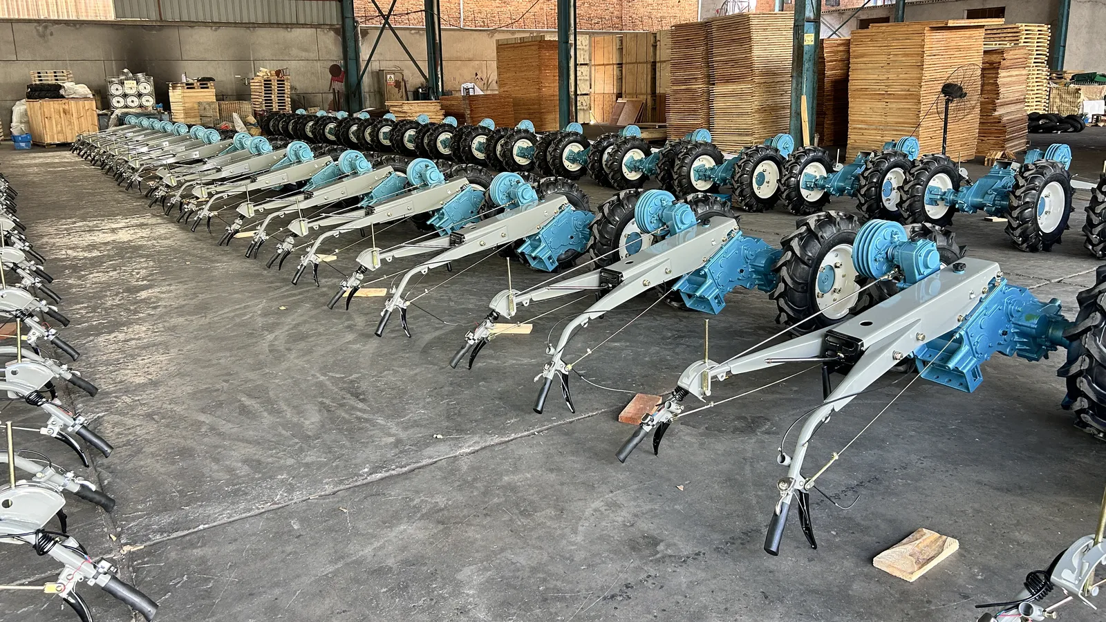
Two kinds of implement order go wrong in ways that never show up on a quotation. One is an implement too heavy for the platform it is going on. The other is an implement of reasonable weight that hangs in the wrong place — and the second is harder to argue about, because the numbers on the two specification sheets look fine.
A two-wheel tractor has no third point of support and no three-point linkage to absorb the difference. It balances on two driven wheels, and the implement's mass arrives at the far end of a lever whose pivot is the axle. That is why a power tiller weight and balance question is never really "how many kilos". It is where the kilos sit, how much of them reach the soil as grip, and what they cost the operator at the end of every pass.
What implement weight and balance mean on a two-wheel tractor
Weight is the easy half. It is the mass the engine, the frame, the wheels and the implement add up to, and a distributor can read most of it off a datasheet.
Balance is the half that decides whether the machine is usable. It is the position of the centre of gravity relative to the drive axle — how much of the total mass is carried ahead of the axle, how much behind it, and how far behind. Two machines of identical weight can behave like different classes of equipment if one has its mass over the wheels and the other has it hanging a metre behind them.
On a machine with four wheels and a mounted implement, the industry answer to that problem is a weight split between front and rear axles, and a documented one: extension guidance for two-wheel-drive tractors puts a towed load at roughly 25% front / 75% rear, a semi-mounted implement at 30/70 and a fully mounted implement at 35/65, and notes that a drive axle can carry up to 120% of its static load once draft is pulling (K-State Research and Extension, MF588). That convention is genuinely useful — and it does not transfer directly, because a four-wheel tractor has a front axle to hold the nose down and a two-wheel tractor has an operator's arms instead.
Search summaries of this question often quote a 40:60 or 50:50 front-to-rear split, with 50–150 lb of front ballast hung on the nose to achieve it. Those are garden-tractor numbers. A machine with one axle has no front axle to divide the weight between and nothing at the nose to hang a suitcase weight on, which is why the work has to be done at the mounting face and the handles instead.
So the useful model for a walking tractor is simpler. There are three places mass can act, and only one of them touches the ground.
Where the weight actually sits: three load points
Every balance problem on a two-wheel machine resolves to these three points. The useful question for each is not "how much weight" but "how far from the axle does it act".
Load point | What it carries | What changes when mass moves there | What the operator feels |
|---|---|---|---|
Drive axle and wheels | All of it — the only contact with the soil | Grip rises directly; nothing about the machine's geometry changes | Better bite, and a machine that digs in instead of riding up |
Implement mounting point | The implement's own mass, plus the reaction from the soil it is working | The centre of gravity moves away from the axle; the nose lifts as the tines load up | Heavier pull on the handles, a machine that wants to run wide in a turn |
Handlebars | Whatever the operator's arms are holding down | The operator becomes part of the counterweight, and part of the fatigue budget | Sore forearms, and a working depth that drifts as the operator tires |
On the two platforms in question the engine is carried at one end of the frame, the implement mounts on the face at the other end, and the drive wheels sit between them. That layout is deliberate: it puts the engine's mass where it can be transferred to the driven wheels, and it keeps the operator behind the working point, where the handles can control depth. It also means the implement is working at the longest lever arm on the machine. Every kilogram bolted to that face does more to the balance than the same kilogram anywhere else on the frame.

Two consequences follow, and both are practical rather than theoretical.
The first is that the implement's weight and its overhang are separate variables. A wide rotary tiller with its mass close to the mounting face and a narrow plough on a long frame can weigh the same and behave completely differently, because the moment — mass times distance from the axle — is what the machine reacts to.
The second is that the operator is part of the balance equation, and the cheapest part to adjust. Handle height and the pressure applied through them set working depth on a machine without a hydraulic lift, which is why two operators running the same combination will report different traction problems on the same field.
How a mounted implement moves the centre of gravity
Picture the machine standing on its wheels with the engine fitted and nothing on the mounting face. The centre of gravity sits over or near the drive wheels, and the machine is close to neutral: it stands, it steers easily, and there is very little weight on the handles.
Bolt on a rotary tiller and three things change at once. Mass moves behind the axle, so the centre of gravity moves back with it. The engine end becomes lighter, which is what allows the tines to follow the ground instead of being levered out of it. And when the tines bite, the soil pushes back against the frame, the machine pivots about the axle, and the engine end lifts. The handles are what hold it down.
That third effect is the one that surprises buyers. A heavier implement does not simply "pull harder". It converts the implement's mass into handle load, and handle load into operator fatigue, and it does so in proportion to how far the working point sits from the axle.
Trailers behave by the same rule with a different sign. A loaded trailer puts its tongue weight onto the hitch, which is behind the axle, which loads the rear of the machine and lightens the front. The number that matters is not the trailer's gross weight but the tongue load and the height at which it is applied — the same interface question that a towing package has to answer before the coupling is specified, which is what the walking tractor trailer and towing hitch guide works through in detail.
There is a limit to how far this can be managed by adding weight at the other end. Bolting mass to the front of the frame to "rebalance" a heavy rear implement raises the total mass without adding anything the wheels can use, and on soft ground it makes the machine sink sooner. Balance work is worth doing on the machine side; over-correction is not.
Weight reaches the soil as traction, not as power
An engine's output only becomes work if the wheels can transmit it. On a two-wheel tractor the tyre-to-soil interface is the entire transmission, and it is why weight is a performance specification rather than a shipping detail — and why, on wet ground, a different wheel can change traction more than any amount of ballast, as the wet-field traction wheel guide sets out.
The clearest published statement of this comes from a drawbar study of a popular Indian walking tractor: the authors attribute the low drawbar power of these machines to "the low weight of walking tractors and the use of small size pneumatic tires as traction devices" (Journal of Terramechanics, 2005). The same study measured what happens when that weight is added at the wheels rather than the frame. On tilled land, fitting 40 kg of wheel ballast to an 8.95 kW walking tractor raised drawbar power by 0.170 kW at rated engine speed and by 0.139 kW at three-quarter rated speed with pneumatic wheels; with steel wheels the same ballast produced 0.315 kW and 0.192 kW respectively. Wheel slip, in the same tests, rose as draft rose.
The direction of that finding is consistent across the literature, and so is its ceiling. A light power tiller development programme reported that a 4.10 kW machine working with a three-bottom mouldboard plough and a five-tyne cultivator developed a maximum pull of 1,333.75 N with 60 kg of ballast and cage wheels (NaCoMM 2011, CMERI). The same paper records an earlier finding that a roughly 200 kg power tiller was judged inadequate to develop a 150 kg pull, and that the recommendation was to roughly triple the machine's weight — a recommendation no distributor would accept as a product, because it describes a machine that has stopped being a walking tractor.

Two practical readings follow.
Slip is the measurement, not the opinion. Agricultural extension guidance for two-wheel-drive tractors puts best tractive efficiency at roughly 13–15% wheel slip under full load, and gives a method any dealer can run with two stakes and a paint mark: count wheel revolutions over a measured distance with the implement raised, count them again with the implement working, and compare (University of Kentucky, AEN-93). The same arithmetic applies to a walking tractor, and it turns an argument about ballast into an observation.
The band is a four-wheel reference point, not a walking-tractor specification. Published two-wheel work runs higher: the drawbar study above calculates its figures up to 25% wheel slip, and a 7.46 kW two-wheel tractor trial cited in the same development paper reported drawbar power at 18% slip. What transfers from the extension guidance is the method and the direction of the correction, not the number — a walking tractor that pulls steadily at 18% slip is not automatically under-ballasted.
When slip is already low, weight is the wrong lever. If the wheels are turning at 8% slip and the machine still will not hold depth, the constraint is draft, not grip — implement type, width, depth or soil condition. The guide to soil resistance, power and weight takes that half of the decision apart. Adding ballast at that point buys nothing and costs fuel, soil structure and operator effort.
Turning: what a heavier implement costs at the headland
Turning a two-wheel tractor is not steering in the four-wheel sense. There is no steering wheel and no Ackermann geometry: the machine turns by disengaging one drive wheel through a steering clutch — the M80 specification sheet records the dog-clutch type — so the other wheel drags the machine around a pivot that sits roughly under the braked side. Everything the machine weighs passes through that one contact patch during the turn.
That makes turn quality a direct function of mass and balance:
- More mass behind the axle means more mass to swing. The pivot is at the wheels; the implement is at the end of the frame. A heavier implement lengthens the arc that has to be dragged around every headland.
- A wide implement increases the swept area even when the radius stays the same. The turning circle you need is the machine's plus the implement's, measured to the outermost point, not to the wheels.
- Loose headland soil multiplies the cost. The outer wheel is doing the work of turning, and it is doing it on ground that has just been worked. Slip at the headland is usually worse than slip in the pass.
Published measurements of walking-tractor turning are worth reading for the magnitude. A study of a walking tractor and trailer combination measured a turning radius of 6.2 m to 7 m at 3, 4 and 5 km/h with the original handle arrangement; relocating the handles to the trailer brought that down to between 2.7 m and 3 m at the same speeds (CIGR Journal, 2011). Very little of that change came from the machine's weight. Most of it came from the control geometry: with the original layout the handle swung out of reach at extreme turns — 1,700 mm from the seat, inclined at 46° — and the operator had to step down and steer standing.
The lesson transfers to implements without a trailer. If the machine's handles have to be pulled through a wide arc, or if the operator is leaning sideways to hold a turn at the end of a pass, the limiting factor is often reach and posture before it is mass. But mass sets the floor: a heavy implement on a long mounting face raises the effort required for the same turn, and it does so on every single one of them. How much room a turn actually needs — measured rather than assumed — is the subject of the field access and turning space guide.

Reading machine weight off a specification sheet
Most weight arguments between a distributor and a buyer start with two numbers that are not comparable. A customer specification sheet typically records the chassis weight without engine, because the engine is a separate choice on the same platform. The machine in the yard is chassis plus engine plus implement plus whatever fluid is in the tyres.
Take the two platforms in the current range, using the figures the customer specification sheets record.
Figure | M80 platform | GN12 / Super 12 platform |
|---|---|---|
Chassis weight, without engine | 179 kg | 470 kg |
Engine reference weight | 89 kg (RT90DI diesel) | Not recorded as a single figure in the sheet |
Overall dimensions | 2,050 × 710 × 1,235 mm | 2,950 × 980 × 1,240 mm |
Wheel track settings | 390–780 mm | 810 / 750 / 690 / 630 / 570 mm |
Working width, rotary tiller | 480 mm standard (14 blades); 600 mm maximum (16 blades) | Sheet records the 600 mm configuration (18 or 24 blades) |
Ground clearance | — | 210 mm |
Two cautions on that table. The working-width figures are the two the client confirms for the range — 480 mm and 600 mm — and the GN12 sheet as supplied records the 600 mm configuration specifically, so a quotation that lists 480 mm on that platform is describing an option rather than what the sheet says. And the chassis weight is a bare frame: the moment the engine, wheels, guards and implement are on it, the machine is a different number, which is why "how much does a tiller weigh" has no answer without a configuration attached to it.

Working width deserves one more sentence here because it interacts with balance. A 600 mm cut takes a wider bite, which raises draft, which raises the slip a given machine weight has to control. The trade between width, depth and available grip is worked through in the power tiller working width article; the point for this article is simply that a wider implement makes the machine's weight matter more, not less.
If the sheet you have been handed does not separate those numbers — chassis weight, engine, implement, track setting — that is the first question to send back. The guide to reading power tiller specifications sets out which fields have to be on the page before a weight figure means anything.
Ballast and counterweight: what can be added, and where
There are four ways to add mass to a walking tractor, and they are not equivalent.
Wheel weights add mass at the axle. This is the most efficient form on a two-wheel machine: it increases the normal load on the driven wheels, which is what produces traction, without moving the centre of gravity rearward or lengthening the lever arm at the implement face.
Liquid ballast in the tyres does the same job with a different mass distribution — it sits low in the tyre and it rotates, so it adds load without adding much to the machine's static height. It is also the hardest to remove when the season changes.
Frame or front counterweights move the centre of gravity. Used at the implement end they make a heavy implement worse; used at the engine end they can restore a usable attitude, at the cost of total mass the wheels did not need.
Operator position is the informal fourth. Standing forward, leaning on the handles, or hanging a tool bag on the frame all change the balance — and none of them appear in a quotation.
Before any of them are added, four checks decide whether adding weight is the right answer at all.
- Is the problem slip or depth? Measure slip first. Around 13–15% under load the machine is in the working band used by four-wheel 2WD guidance; below about 10% it is over-ballasted for the conditions and the constraint is elsewhere. Walking-tractor trials run higher, so treat the top of that band as a floor for the question rather than a target to hit.
- What does the platform allow? Wheel and frame ratings are a manufacturer question, not a workshop one, and the answer belongs in writing before the weights are ordered — the M80 platform page carries the current configuration figures for that chassis.
- What does the extra mass do to the implement setting? Working depth is set by the mounting and the handles; more mass on the rear changes the attitude the implement works at, so depth has to be re-set after ballast is added, not before.
- What does it do between plots? Weight added at the wheels can usually be carried; weight bolted to the frame changes how the machine is moved, loaded and handled. The lightweight power tiller programme cited earlier treated the ability for two people to lift the machine between plots as a design requirement for terrace and hill work, and ballast quietly deletes that property.
A fifth check belongs to the distributor rather than the machine: whether the ballast is being added to fix one customer's field or is about to become the specification for every unit in a market. Weight is easy to add and expensive to remove from a product line.
Weight added at the wheel buys traction. Weight added behind the axle buys a different problem. The two are not interchangeable, and only one of them comes off again in a morning.
Balance on slopes, bunds and narrow fields
Slope work changes which axis matters. On flat ground the balance question runs front to back; on a side slope it runs left to right, and the lever available is not ballast but track width.
Both platforms offer a range of track settings — 390 mm to 780 mm on the M80, five positions between 570 mm and 810 mm on the GN12 — and widening the track is the cheapest stability measure available, because it lowers the height-to-width ratio without adding mass. It also costs turning room and changes where the wheels run relative to the previous pass.
The weight question on slopes is usually about total mass, not distribution. The CMERI programme makes the trade explicit: it records that most power tillers manufactured in India at the time were in the 8–10 hp range and weighed about 400 kg, and that machines of that weight were poorly suited to hilly areas because of limited manoeuvrability — which is what justified developing a lighter machine for terraces and orchards. An orchard or row-crop buyer makes the same trade from the crop side: the narrower, lighter machine that fits between rows is usually the one that still steers at the end of them.
Bunds and field edges are where balance failure becomes visible. A turn taken with a heavy implement on the outer wheel loads a narrow strip of soil with the whole machine's mass and the turning force together; repeat it every pass and the bund edge fails and the machine steps down. Working practice — lifting the implement for the turn where a lift is fitted, taking the turn wider than feels necessary, keeping the outer wheel on firm ground — does more for this than any ballast change.
The terrain side of the same decision, including what a lighter platform buys on terraces and narrow plots, is set out on the hilly and small-field application page.
A balance check you can run before the order
Everything above is measurable with a tape, a paint mark and a notebook. This is the sequence worth handing to a dealer who has to specify a combination for a customer.
Step | What you do | What the reading tells you | What to change first |
|---|---|---|---|
1 | Write down both weights: chassis without engine, and the engine reference the customer chose | Whether the "machine weight" in the discussion is the shipped machine or the bare frame | Get the second number before quoting anything |
2 | Measure the implement's overhang — from the centre of the drive axle to the working point | The lever arm. Two implements of equal mass are not equivalent if one sits 200 mm further back | Choose the implement with the shorter arm when draft and handling are both marginal |
3 | Measure wheel slip at working load: mark a wheel, count revolutions over a measured distance raised and working | Where the combination sits against the 13–15% reference band (four-wheel 2WD guidance; walking-tractor trials read higher) | Below 10%: stop adding weight. Above 20%: add mass at the wheels or reduce draft |
4 | Measure the turning circle with the implement fitted and at working depth, to the outermost point | Whether the headland actually fits the machine as configured | Track setting, implement width, or the field plan — in that order |
5 | Record the track setting and handle height used for the measurements | Makes the numbers reproducible; most "it behaved differently" reports trace back to an unrecorded setting | Fix the setting and re-measure before changing anything else |
The sequence is deliberately ordered so that the cheapest change comes last. Steps 1 and 2 cost nothing but a conversation and a tape measure. Step 3 costs an hour in a field. Steps 4 and 5 cost an afternoon. A distributor who runs them in that order can usually answer the customer's question without ordering a single part — and when a part is needed, the order can state which problem it solves. Fitment questions that are not about mass — bolt patterns, mounting faces, drive connections — belong to the implement compatibility checklist.
What to put in the enquiry
A balance question asked in words produces a brochure. The same question asked in numbers produces a configuration. Five lines are enough:
- The platform and engine you intend to fit, with the chassis weight and the engine reference.
- The implement, its approximate mass, and how far its working point sits from the drive axle.
- The working width and depth you expect to run, in millimetres.
- The field condition: soil type, typical moisture, and whether the machine will work puddled, dry or both.
- The turning space at the headland and the narrowest access the machine has to pass.
Those five lines let a supplier answer with a configuration instead of a price list, and they let a distributor defend the choice two seasons later when a customer asks why the machine was specified the way it was. If the enquiry goes through a form rather than an email, the power tiller RFQ builder collects the same five fields.
SUNTEC builds two-wheel power tillers of this class on the M80 and GN12 platforms, so a configuration question that starts with those five lines is one we can answer against the specification sheets rather than against a catalogue description. If you would rather work through your own numbers before committing an implement order, send us the weights, the overhang and the field condition and we will check the combination with you. How the other implements in the range fit around the same platform is covered in the implements and attachments selection guide.
Balance is set long before the container is loaded. It is set when someone decides which implement goes on which platform, and whether the machine that arrives in the dealer's yard can turn at the end of a row without the operator stepping off. The numbers for that decision are small in number and cheap to take. They are worth taking before the order, because after the order they become an argument about a machine that is behaving exactly as its weight distribution said it would.